yo,
work's been hell for a bit so i took a week off and finally got some of my own stuff done, the main thing being another synth module...
")


this one's an lfo. since i finished the dual vcf i'd been thinking i should build an lfo to modulate the cutoff, so i got to looking at designs and initially settled on doing something based on the mfos variable skew lfo. with square, triangle and sine outputs, as well as the titular "variable skew", it seemed like it did basically everything i wanted, with one exception: it doesn't have a sync input, which i was set on having for eg. keeping the lfo in step with each note sent from my sequencer
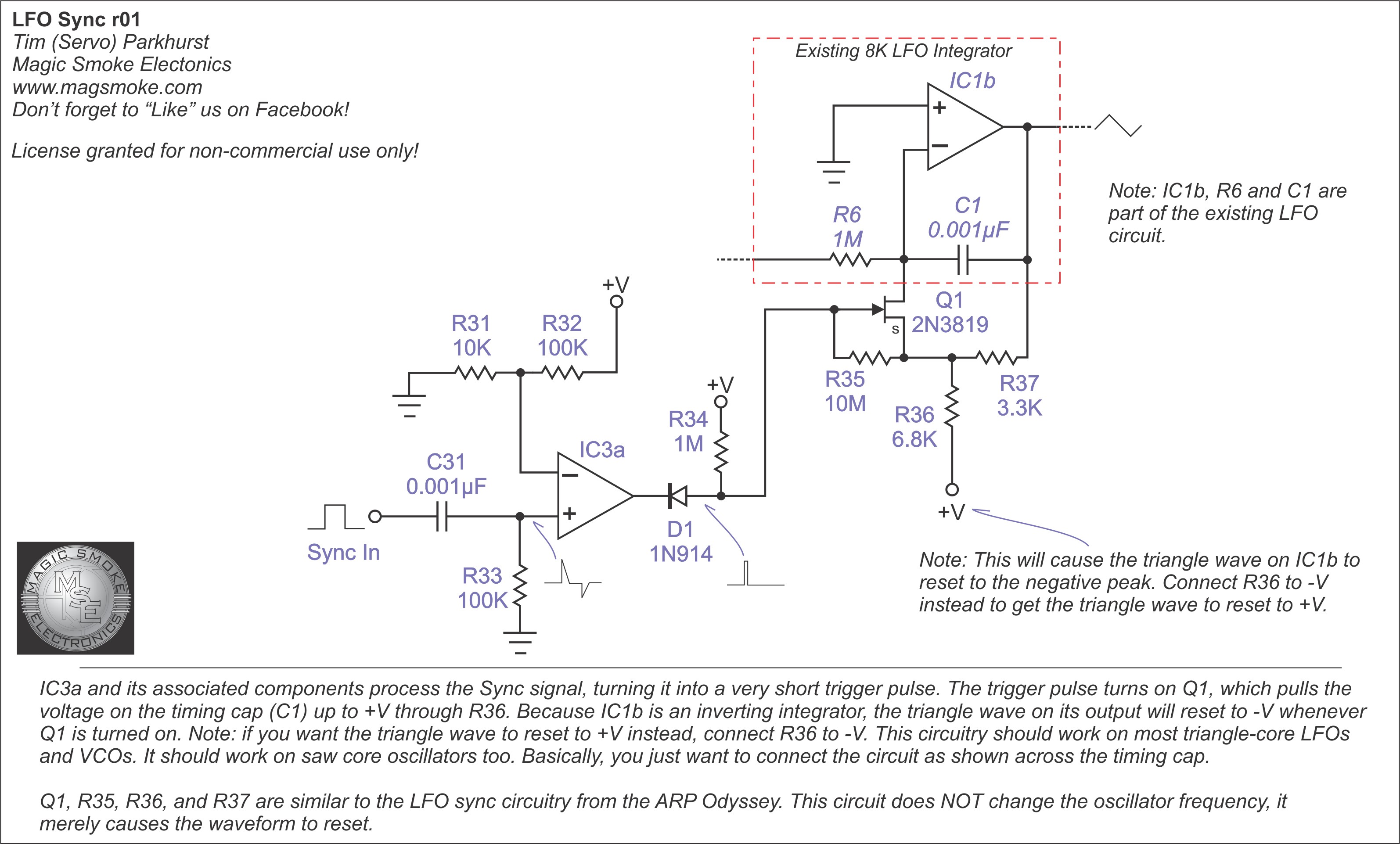
i did some searching about for a circuit that could do it, but the magic smoke electronics design i saw posted everywhere didn't seem to work on account of the timing cap(s) for the variable skew lfo being too big to charge fully before the reset pulse ends. this was kind of a dealbreaker to me, so instead i took the core of the cgs utility lfo and replaced the additional square and mix outputs with a sine output (using an adaptation of eddy bergman's adaptation of thomas henry's triangle-sine converter) and the lfo sync circuit mentioned above
the result is, not exactly equivalent to the mfos design. but it's good enough for audio work....?1 so far i've tried using it for controlling vcf cutoff as well as the vco's pitch mod & pulse mod and gotten some weird and/or cool sounds, but i think i'm gonna need to throw together an attenuator so i can tone the lfo output down a bit cos modulating the other modules by a full +/-5v is A Little Much. maybe i'll manage to throw one together with the rest of my time off? who can say..
as for the actual construction of the module, that was a total mess. i was really unfocused while designing it and while making the circuit itself due to overflowing burnout from work, so when i finally got it all together it didn't work right and debugging it was a nightmare. first i got nothing out of it, which i quickly realised was because i'd installed the diode for the -12v rail backwards, then i wasted like 3 hours trying to figure out why the triangle output was clipping, only to realise it was because, after missing the power smoothing caps off of the stripboard layout, i'd then added them to the circuit in the wrong place and had one of them pulling pin 12 of the tl074 up to +12v. with that fixed and the outputs finally looking normal i thought i was done, but instead noticed that the frequency changed at random whenever i poked some of the panel wiring. i figured it was being caused by a short so i cleaned up some solder joints on the back which seemed to fix it, but... more on that later....
i was ready to call it there, but after some more testing i found that the manual trigger button only worked the first time i pressed it, and wouldn't work again until i'd power cycled the module. thankfully i got lucky fixing this one, as i noticed that bridging the button side of c7 to ground with my finger made it work again, which made me realise the issue was that the side in question was left floating once the button had been released, presumably preventing it from draining enough to generate more signal pulses. i considered swapping the button for an on-(on) spdt switch with the other side tied to ground, but it turns out i don't actually have any of those2, so i just shoved in the biggest resistor i have to ground instead and that seemed to work fine. after playing with the circuit in a simulator i think that maybe i should've used a lower value instead since the 10M i went with seems to intermittently cause the pulse to trigger a second time when the button is released, but my oscilloscope doesn't have the resolution i'd need to check if it works that way irl so.... 🤷♀️
after that i went to bed, and the next day i went to install the module in my rack, only to find that my woes were not over: the frequency was going wild & wacky again. after a lot of poking around, i started to suspect that the frequency pot itself was the cause, so i swapped it and.... yeah that was totally it. not sure how that happened but i suspect i managed to damage it somehow while i was diagnosing the second issue. or maybe i just got solder in it. i held onto the pot so i could investigate at some point, but for now it remains a mystery
so yeah, that's how i wasted most of 2 days fiddling with a module i'd already finished building. as usual i've put it on the synth page and the repo so check it out or dont. either way, heres some other updates before i end this blog post
module schematics
like i mentioned in the post about my vcf, i had to learn kicad to simulate the behaviour of the vcf so i decided i should probably just go ahead and apply that knowledge to make real circuit diagrams for each of my modules. well i've finally made a start on it! circuit diagrams for the vcf, lfo and passive multiple3 are now up on the repo. i'll do the rest eventually, although idk if i'll bother blogging about it once i finish so keep an eye out if ur interested
minor site updates
v3 of "cool goth zone" has been up for just over a year now, but since i was in such a rush at the time trying to get it out before cohost shuttered4 i never got round to adding some of the basics. i've been meaning to fix this for a while but didn't have the time or energy, so a couple days ago i decided to use my time off to finally sit down with it and add favicons and (somewhat limited) link previews. i might come back to the link previews and make them show like, more info for eg. blog posts at some point? but i think im done programming for this week.
ok thats everything. im out. see u in the next one!
– freya
-
past freya wrote this phrase in the readme for the module a few days ago. no idea what it meant by this but i like how it sounds so, ↩
-
also for some reason they only seem to be available in red?? all the other buttons on my modules are black. its gotta stay coordinated. ↩
-
not that the passive multiple really needs it since it's literally just 8 jacks wired together. but it's low hanging fruit so why not ↩
-
rip little purple dude. miss u every damn day.. ↩